In a cellular system, handover can be defined as a procedure to transfer a User Equipment (UE) and its context from a source cell to a target cell when source cell signal becomes bad so it handover the UE to target cell to continue the UE session.
In LTE, Handover Mobility Support for UEs in ECM-CONNECTED handles all necessary steps for handover procedure. These steps can be broadly classified as follows:
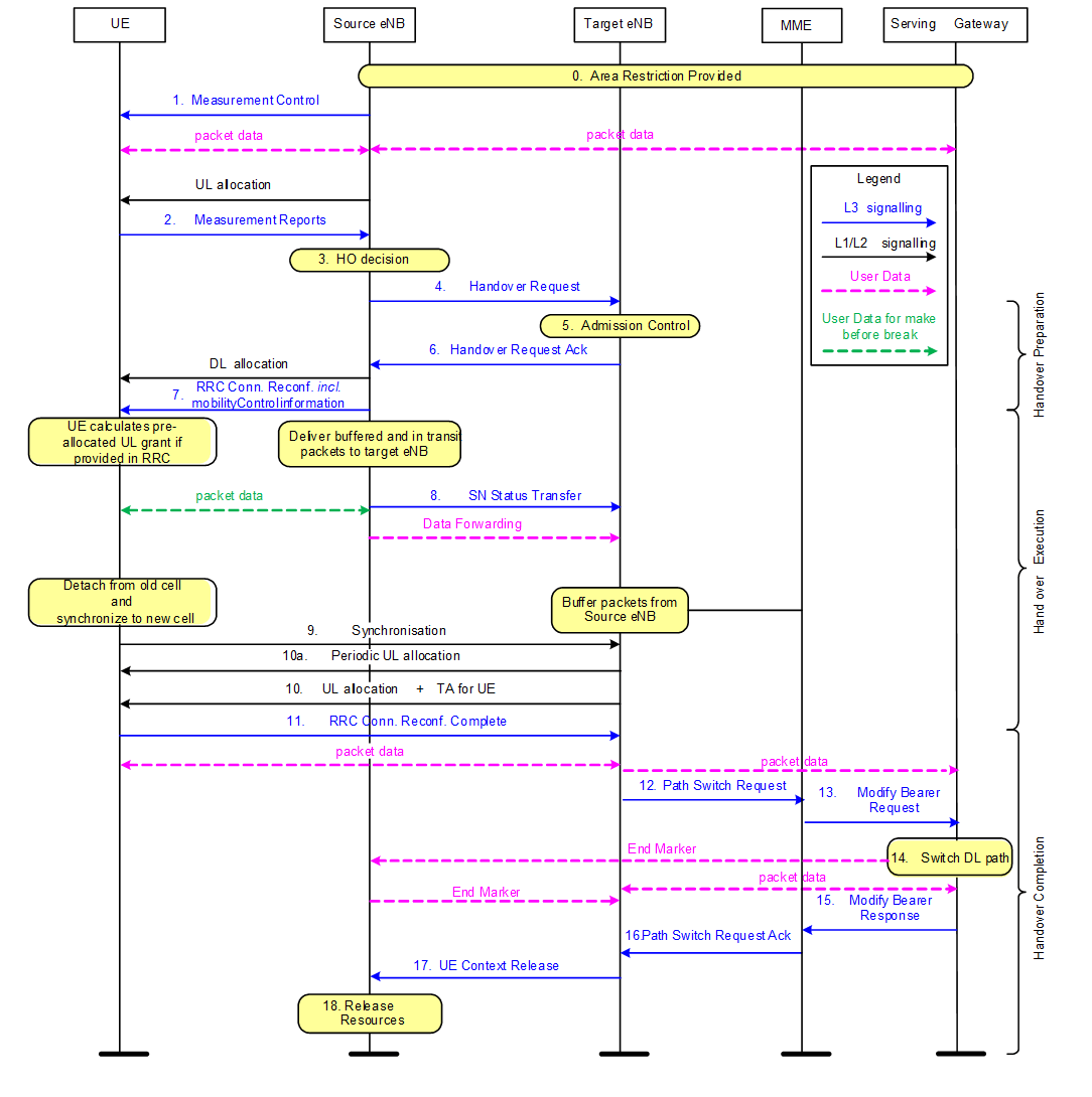
- Handover Preparation includes steps HO decision on the source cell (control and evaluation of UE and eNB measurements taking into account certain UE specific area restrictions) and preparation of resources on the target cell (Step# 1 to Step #6)
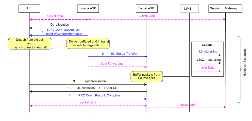
- Handover Execution steps involve in commanding the UE to the new radio resources (Step# 7 to Step# 11)
- Handover Completion steps involve releasing resources on the (old) source cell (Step# 12 to Step# 18)
The figure below depicts the basic handover scenario where neither MME nor Serving Gateway changes.
Handover Latency :
Handover Latency is one of the measures of system performance. As per 3GPP 36.881, the handover latency can be measured by the time UE received handover command (RRC Connection Reconfiguration Incl. mobilityControlInfo) from the source cell and it sends RRC Connection Reconfiguration Complete to a target cell. In other words, we can say the handover latency is the time taken during handover execution step.
Handover Latency Calculation:
Let’s discuss what are the component contributes to handover latency and these involve all the steps associated with handover execution i.e. form Step 7 to Step 11.
Step 7: RRC Connection Reconfiguration Incl. mobilityControlInfo: In this step, the UE receives the RRCConnectionReconfiguration message with necessary parameters (i.e. new C-RNTI, target eNB security algorithm identifiers, and optionally dedicated RACH preamble, target eNB SIBs, etc.) and is commanded by the source eNB to perform the HO [12]. RRC procedure delay includes RRC Connection Reconfiguration including mobilityControlInfo as well as related reconfigurations, including
- Layer 2 reset / reconfiguration
- Reset MAC
- Re-establish/reconfigure PDCP and RLC for all RBs that are established.
- Enable integrity protection and ciphering of RRC messages.
- Layer 3 reconfiguration (e.g. measurement configuration)
As per section 11.2 of TS 36.331, for handover, the maximum allowed delay for RRC procedure is 15 ms.
Step 8: SN Status Transfer: In this step, the source eNB sends the SN STATUS TRANSFER message to the target eNB to convey the uplink PDCP SN receiver status and the downlink PDCP SN transmitter status of E-RABs for which PDCP status preservation applies (i.e. for RLC AM).Since this is eNB to eNB signaling which is not related to the air interface and it can be done in parallel with step 9 below, the delay contribution of this step can be considered negligible total handover latency.
Step 9: Synchronization After receiving handover command (i.e., Step 7: RRCConnectionReconfiguration message including mobilityControlInfo), the UE may perform the following in this step
- Physical layer synchronization and reconfiguration
- Start synchronizing to the DL of the target PCell.
- Reconfigure physical layer
- Access the target cell via RACH (following a contention-free procedure if a dedicated RACH preamble was indicated in the mobilityControlInfo, or following a contention-based procedure if no dedicated preamble was indicated)
- Layer 2 reconfiguration
- Security key update: UE derives target eNB specific keys and configures the selected security algorithms to be used in the target cell.
According to TS 36.133, when the UE receives an RRC message implying handover the UE shall be ready to start the transmission of the new uplink PRACH channel within Dhandover seconds from the end of the last TTI containing the RRC command, where Dhandover is the sum of RRC procedure delay and the “interruption time”. The interruption time is defined as the time between the end of the last TTI containing the RRC command on the old PDSCH and the time the UE starts transmission of the new PRACH, excluding the RRC procedure delay.
Interruption time includes:
- Target cell search
- UE processing time for RF/baseband retuning, derive target eNB specific keys, configure security algorithm to be used in the target cell
- RACH procedure related (uncertainty delay to acquire RACH opportunity followed by PRACH preamble transmission)
Step 9.1: Target cell search: As, in most cases, the target cell is selected based on UE measurement reports and can be assumed to be “known”, the delay due to this step can be considered to be 0 ms for this study.
Step 9.2: UE processing time for RF/baseband re-tuning, security update: While the exact value can vary significantly based on various parameters, for the purpose of this SI, we consider UE processing time (for RF/baseband re-tuning, derive target eNB specific keys, configure security algorithm to be used in target cell) to be 20 ms as defined in TS 36.133.
Step 9.3: Delay to acquire first available PRACH in target eNB: Considering a typical RACH configuration where PRACH is available every 5 subframes, the minimum delay for this step 0.5ms and a typical delay would be 2.5 ms.
Step 9.4 PRACH preamble transmission: The last delay element in step 9 is 1 subframe required for PRACH preamble transmission i.e. 1 ms
Step 10: UL Allocation + TA for UE
In this step, the target eNB responds with UL allocation and timing advance. This corresponds to RAR from target eNB.Assuming LTE FDD and that subframe number is continuously numbered, if UE sends RACH preamble in subframe n, following current specification, eNB can send RAR as early as in subframe n+3 (section 5.1.4 of TS 36.321). Assuming that the grant decoding and/or TA delay is not included in this step, the minimum delay of this step would be 3ms and typical/average delay would be 5ms.
Step 11: UE sends RRC Connection Reconfiguration Complete: When the UE has successfully accessed the target cell, the UE sends the RRCConnectionReconfigurationComplete message (C-RNTI) to confirm the handover, along with an uplink Buffer Status Report, whenever possible, to the target eNB to indicate that the handover procedure is completed for the UE. The target eNB verifies the C-RNTI sent in the RRCConnectionReconfigurationComplete message. The target eNB can now begin sending data to the UE.
According to section 6.1.1 of TS 36.213, UE can then send RRCConnectionReconfigurationComplete as early as after k1 >= 6 subframes, i.e., the delay of this step is typically 6 ms. This includes UE Processing Delay (decoding of scheduling grant and timing alignment + L1 encoding of UL data) and transmission of RRC Connection Reconfiguration Complete.
| Component/ Step | Description | Time (ms) |
| 7 | RRC Connection Reconfiguration Incl. mobilityControlInfo | 15 |
| 8 | SN Status Transfer | 0 |
| 9.1 | Target cell search | 0 |
| 9.2 | UE processing time for RF/baseband re-tuning, security update | 20 |
| 9.3 | Delay to acquire first available PRACH in target eNB | 0.5/2.5 |
| 9.4 | PRACH preamble transmission | 1 |
| 10 | UL Allocation + TA for UE | 3/5 |
| 11 | UE sends RRC Connection Reconfiguration Complete | 6 |
| Minimum/Typical Total delay [ms] | 45.5/49.5 |
It should be noted that the above values assume successful transmission at first attempt. This may not always be true especially for handover scenarios where channel quality may be degraded. The actual delay values can be higher if some steps require re-transmissions.
References:
- 3GPP TS 36.300 V8.12.0 E-UTRA Overall Description
- 3GPP TR 36.881 v 14.0.0 Study on latency reduction techniques for LTE