7.Transmit Power Control ( NR Physical Layer Specifications in 5G)
7.1 Transmit Power Control Taking Beam Control into Consideration ( NR Physical Layer Specifications in 5G)
In NR, Transmit Power Control NR Physical Layer Specifications in 5G, since transmitting/receiving beams can be formed in both the base station and the user equipment, transmission power control is specified by taking into consideration the beamforming op- eration, which causes beamforming gain variation when switching the transmitting/receiving beam.
The user equipment can use reference signals to which the transmitting/receiving beams are ap- plied in order to estimate the path loss including the beam gain. Specifically, the path loss is estimat-ed by comparing the transmit power before apply- ing the transmit beam with the received power af- ter applying the receiving beam. By applying dif- ferent transmitting/receiving beams to multiple ref- erence signals, the reference signal to be used can be dynamically switched to adapt to path loss fluc- tuations caused by switching of the transmitting/ receiving beams.
Also, as in LTE, fractional transmission power control is specified as a way of reducing the trans- mit power at cell edges where the path loss is large. For each transmitting/receiving beam, the power control related parameters can be set differently so that the path loss compensation and power off- set can be optimized.
7.2 Distribution of Transmission Power between LTE and NR
Release 15 specifies an upper limit of transmit power based on guidelines for the protection of humans. For the case of simultaneous transmissions of LTE and NR in the same frequency range, the total power between LTE and NR shall be within a specified range of values [1]. In the Release 12 LTE DC, a user equipment can be configured with a minimum guaranteed power
for each CG (cell group), and the user equipment dynamically distributes the transmit power between CGs such that each CG can at least use the mini- mum guaranteed power. However, it is difficult for early commercial user equipment to support this, since it requires dynamic power sharing between LTE and NR transmitters. Therefore, Release 15 specifies a scheme whereby the base station semi- statically configures the maximum transmission pow- er for each CG. The behavior of user equipment for power control could be different depending on whether the user equipment supports dynamic pow- er sharing between LTE and NR.
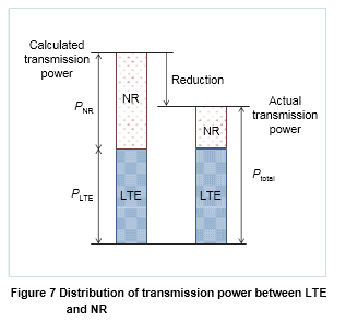
When the user equipment has a dynamic pow- er sharing capability, it adjusts the NR transmis- sion power so that the instantaneous total power does not exceed the specified value. An example of dynamic power distribution is shown in Figure 7. When the maximum transmission power of LTE and NR (P LTE, P NR) and the specified total power
(P total) have been set and the instantaneous calcu- lated total transmission power exceeds P total, the NR transmission power is reduced so that the actual transmission power of the user equipment does not exceed P total.
Note that the base station is able to configure the LTE and NR maximum powers so that their total exceeds the specified value. However, if user equipment does not have the ability to perform dy- namic power sharing, its uplink transmissions will be performed using time division multiplexing to switch between LTE and NR.


