4.1 MIMO Transmission Method (MIMO/Beamforming / NR Physical Layer Specifications in 5G)
In the high-frequency band, it is very important to obtain a high beamforming gain(Gain: One of the radiation characteristics of an antenna. An indicator of how many times larger the radiation strength in the antennaʼs direction of peak radiation is relative to a standard antenna) by using many antennas to compensate for the effects of radio wave attenuation. The high-frequency band of NR re-quires the use of Multiple Input Multiple Output.
MIMO/Beamforming / NR Physical Layer Specifications in 5G.
(MIMO) (MIMO: A signal transmission technology that improves communication quality and spectral efficiency by using multiple transmitter and receiver antennas to transmit signals at the same time and same frequency) technology that assumes the availability of hybrid beamforming using up to 256 antenna elements at the base station and up to 32 antenna elements at the user equipment.
Hybrid beamforming is a technique that can reduce the cost of implementing circuits for beamforming in high-frequency bands. It consists of digital beamforming to perform signal control in the baseband, and analog beamforming to perform signal control in the RF (Radio Frequency). Since analog beamforming cannot be controlled in sub-band units due to implementation constraints, wideband beamforming is generally used.
To improve the spectral efficiency (Spectral efficiency: The number of data bits that can be transmitted per unit time and unit frequency band.), it is Essential to use spatial multiplexing in addition to beamforming. For the downlink, codebook ( Codebook: A set of predetermined precoding weight matrix candidates.) based closed-loop(Closed-loop: A method of using feedback information from receivers.) precoding ( Precoding: A process for improving the quality of signal reception by multiplying signals before transmission with weights according to the current radio propagation channel) is specified to accommodate up to eight layers of single-user MIMO (Single-user MIMO: Technology that uses MIMO transmission identical temporal frequencies for a single user.) and up to
twelve layers of multi-user MIMO ( Multi-user MIMO: Technology that uses MIMO transmission at identical temporal frequencies for multiple users). For the uplink, two transmission methods are supported, namely codebook-based and non-codebook-based transmission. It is possible to transmit up to four layers with single-user uplink MIMO. The non-codebook- based transmission method is designed by assuming beam reciprocity (Beam reciprocity: A technique whereby radio equipment determines which transmitting beam to use based on information derived from the received beam) is supported in the user equipment. The user equipment receives a downlink reference signal (RS) such as SS/PBCH blocks or Channel State Information RS (CSI-RS) (CSI-RS: A downlink reference signal used by the mobile terminal to measure the state of the radio channel.) and determines the uplink precoder based on the received downlink RS.
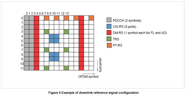
4.2 Reference Signal Structure
The RS structure of NR basically follows that of LTE while achieving the flexibility to adapt to operation in various different frequency bands and scenarios. An example of a downlink RS structure is shown in Figure 4. If an RS is transmitted constantly, it may cause design constraints for possible RS and channel designs in future releases. Therefore, NR tries to avoid specifying an RS that is constantly transmitted (e.g., Cell-specific Reference Signal (CRS) in LTE), and implements the function of CRS by using multiple RSS instead. Specifically, the CSI-RS, DeModulation RS (DM-RS) and Tracking RS (TRS) are specified for channel state information estimation, data demodulation, and time/frequency tracking, respectively.
DM-RS enables suitable tracking of a wide range of channel fluctuation speeds and is specified with a structure having a Front-Load (FL) DM-RS mapped in the front part of the data channel as well as additional mapping of 0‒3 symbols of Additional (AD) DM-RS in order to suppress overheads (Overhead: Control information needed for transmitting/receiving user data, plus radio resources used for other than transmitting user data such as reference signals for measuring received). TRS has the same signal sequence generation with CSI-RS. However, TRS is transmitted in the intervals of 4 subcarriers and 4 OFDM symbols so that sufficient tracking accuracy is achievable with a reasonable overhead. In high-frequency bands, phase noise ( Phase noise: Phase fluctuation that occurs due to frequency components other than those of the carrier frequency in a local oscillator signal) would be a serious issue. Therefore, in NR, Phase-Tracking Reference Signal (PT-RS) is newly specified as a UE-specific reference signal.
4.3 Beam Control Techniques
Beam control in L1/L2 ( The second layer of the OSI reference model (data link layer)) can be divided into beam management and CSI acquisition. Beam management is a particularly effective technique at high frequencies and is generally aimed at establishing and maintaining transmitting/
receiving analog beam pairs between the base station and user equipment. For example, the user equipment compares the L1-Reference Signal Received Power (RSRP) ( RSRP: Received power of a signal measured at a receiver. RSRP is used as an indicator of receiver sensitivity of a mobile terminal.) of multiple SS/PBCH blocks and CSI-RS to which different beams have been applied by the base station, and selects a suitable transmit beam to be reported to the base station. The base station reports the beam information applied to the downlink channel so that the user equipment can select the corresponding reception beam to receive the downlink channel. A beam failure recovery technique is also specified, whereby user equipment that detects deterioration in the characteristics of a base station beam can request a switch to a different beam.
On the other hand, CSI acquisition is used for purposes such as determining the choice of transmission rank (Transmission rank: The number of layers (spatial streams) transmitted simultaneously in MIMO), digital beams and Modulation and Coding Scheme (MCS) ( MCS: Combinations of modulation scheme and coding rate decided on beforehand when performing Adaptive Modulation and Coding). The codebook used for digital beam control is specified as Type I and Type II, which have relatively low and relatively high quantization granularity (Quantization granularity: The spatial granularity of beams that are capable of being formed.), respectively. In Type II, information about two beams and their linear combination ( Linear combination: The linear sum of vectors. The vectors are multiplied by constant factors and added together) information is reported to the base station, enabling beam control with higher spatial granularity.