2.1 Frame Structure/Duplex Mode NR Physical Layer Specifications
Frame Structure/Duplex Mode NR Physical Layer Specifications Support for New Subcarrier Spacings NR adopts a radio access scheme called Orthog- onal Frequency Division Multiplexing (OFDM)( OFDM: A multi-carrier modulation format where information signals are modulated with orthogonal subcarriers. A type of digital modulation scheme where information is split across multiple orthogonal carriers and transmitted in parallel.
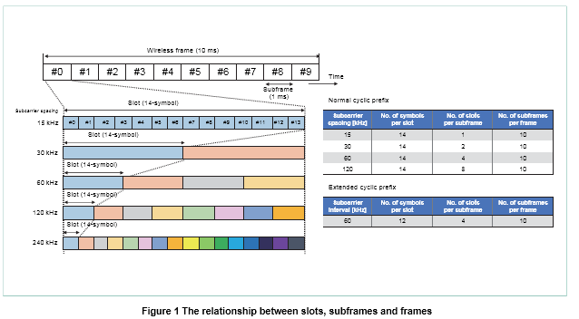
It can transmit data with high spectral efficiency), which is the same scheme used in To adapt to services requiring low latency and to enable the use of higher frequencies (including millime- ter-wave (Millimeter waves: Radio frequency band with wavelengths inthe range of 1 to 10 mm) frequencies), NR supports higher sub- carrier ( Subcarrier: Each carrier in a multi-carrier modulation system that transmits bits of information in parallel over multiple carriers) spacings of 30, 60, 120, and 240 kHz based on the LTE subcarrier spacing of 15 kHz.
Note that a subcarrier spacing of 240 kHz is only used for Synchronization Signal (SS) (SS: A physical signal enabling the mobile station to detect)/Physical Broad- cast CHannel (PBCH) blocks, as described later (In addition, the SS/PBCH block does not support a subcarrier spacing of 60 kHz).
When user equipment initially accesses the net- work, it detects an SS/PBCH block by assuming a subcarrier spacing that can be set in this carrier, and based on the PBCH detected in this block, it identifies the subcarrier spacings of the control/ data channels, etc.
2.2 Frame Structure NR Physical Layer Specifications
In NR, multiple OFDM symbols are used to construct slots, subframes, and frames. A slot consists of 14 OFDM symbols for the given sub- carrier spacing, a subframe is defined as a 1 ms interval, and a frame is defined as 10 subframes. These relationships are shown in Figure 1. In the frequency domain, a resource block con- sists of 12 consecutive subcarriers for the given subcarrier spacing.
In NR, unlike LTE, the frame structure is not dependent on the duplex mode . In other words, it uses a common frame structure regardless of the duplex mode.
NR provides much greater flexibility than LTE in the uplink and downlink patterns of Time Divi- sion Duplex (TDD) communication. It is possibleto semi-statically or dynamically set various up- link/downlink patterns by the system information and/or by user-specific higher layer signalingand/or L1 signaling It is also possible to perform TDD communica- tion without using higher layer/L1 signaling to indi- cate the uplink/downlink patterns.
The user equip- ment can recognize the direction of uplink/downlink communication based on periodic transmission and reception that are configured by higher layer sig- naling and/or indicated by dynamic signaling in the physical layer.
3.Initial Access and Mobility / NR Physical Layer Specifications in 5G
A user equipmentʼs initial access in NR is per- formed according to a procedure that involves the steps of detecting a Synchronization Signal (SS), acquiring broadcast system information, and es-tablishing connection with the network by a ran- dom access procedure.
3.1 SS/PBCH Block
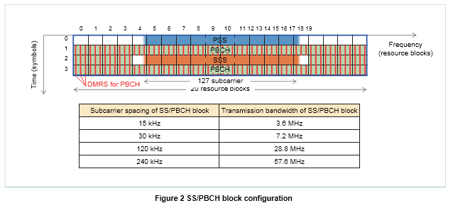
As in LTE, the SS in NR consists of two signals: a Primary Synchronization Signal (PSS), and a Secondary Synchronization Signal (SSS). The SS together with the PBCH and the DeModulation Reference Signals for PBCH (DMRS for PBCH) forms an SS/PBCH block as shown in Figure 2.The base station uses this SS/PBCH block to provide information that is essential for initial access and mobility, including system parameters whereby user equipment can discover NR cells,
establish frame synchronization, measure the downlink re- ception quality, and carry out other actions neces- sary for the reception of system information. The base station can set the transmission timing and transmission period of the SS/PBCH block for each carrier, and indicates this information to the user equipment.
In NR, multiple resources for SS/PBCH block transmission are defined within a half frame of 5 ms duration, where the maximum number of SS/ PBCH block transmissions per carrier depends on the frequency band. As shown in Figure 3, the num- ber of SS/PBCH blocks to be transmitted can be set according to factors such as the base station
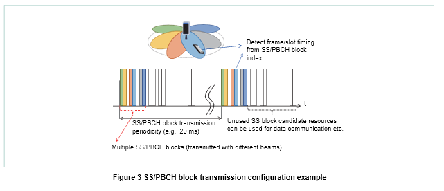
antenna configuration. With multiple SS/PBCH blocks, different beamforming can be applied to each SS/ PBCH block in order to increase the communica-tion range and expand the area of coverage.
3.2 System Information Notification
Broadcast information in NR can be classified into three types: broadcast information transmitted by the PBCH, system information necessary for ini- tial access, and other system information. The PBCH includes a System Frame Number (SFN) and information that user equipment needs to establish frame synchronization with a NR cell after detecting an SS/PBCH block, such as an index for identifying the symbol position of the detected SS/PBCH block in a half frame.
The PBCH also carries system parameters that are needed for the reception of System Information Block type 1 (SIB 1), which is described below. To perform random access, it is necessary to have information such as the uplink carrier infor- mation and random access signal configuration in- formation. This is included as part of the information necessary for initial access, which is broadcast to the user equipment in an NR cell as SIB1.
3.3 Random Access
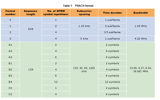
Random access in NR is performed in four steps in the same way as in LTE. At the first step, the user equipment transmits a Physical Random Access CHannel (PRACH) to the base station. As shown in Table 1, NR defines 13 PRACH formats in total, including some formats with fixed subcarrier spacings that follow the de- sign of LTE PRACH, and other formats with vari- able subcarrier spacings that can fit into the dura- tion of an integer number of symbols in an NR slot.
When a base station is operated with beamform- ing, where different beams are applied to multiple SS/PBCH block transmissions, different PRACH transmission resources are associated with differ- ent SS/PBCH blocks. The user equipment transmits a PRACH to initiate random access by using the PRACH resource associated with the selected
SS/PBCH block. In this way, the base station can use the received PRACH resources to figure out which SS/PBCH block (and thus which beamform- ing direction) was received by the user equipment transmitting a PRACH. Therefore, in the subse- quent random access procedure consisting of ran- dom access response reception, connection request message transmission and contention resolution mes- sage reception, the base station can use transmis- sion/reception beamforming directed specifically to the user equipment.
3.4 Mobility
In NR, as in LTE, the base station performs tasks such as selecting serving cells, performing hando- vers and adding/deleting secondary cells based on the report from corresponding user equipment re- garding measurement results on downlink reference signals. The SSS included in the SS/PBCH block transmitted by the base station is a basic cell-specific reference signal in NR. The user equipment uses it to measure and report the Reference Signal Re- ceived Power (RSRP) and Reference Signal Received Quality (RSRQ) in each cell according to settings from the base station.
Also read :- What is Active Antenna System (AAS) and its 3D Aspect, Why AAS for 5G ?